Microsoft Hyper-V Deployment
Explore this Page
- Overview
- Microsoft Hyper-V Models
- SANsymphony Virtual Machine Settings
- Microsoft Hyper-V Deployment Examples
- Microsoft Hyper-V Deployment Technical Notes
Overview
This page provides Microsoft Hyper-V-specific deployment recommendations for SANsymphony hyper-converged infrastructure (HCI) environments, including supported deployment models, virtual machine configuration settings, deployment examples, and technical best practices.
Refer to the Hyper-Converged Virtual SAN Deployment FAQ guidance for general deployment models, architecture considerations, and known issues related to SANsymphony HCI environments.
Microsoft Hyper-V Models
Two different configurations are possible when using Windows with the Hyper-V Role:
Running on the Root/Parent Partition
SANsymphony runs in the root/parent partition of the Windows operating system along with the Hyper-V feature.

Running Inside a Virtual Machine
SANsymphony runs in its own dedicated, Hyper-V Windows virtual machine.

The standalone “Microsoft Hyper-V Server” products, which consist of a cut-down version of Windows containing only the hypervisor, Windows Server driver model, and virtualization components, are not supported.
SANsymphony Virtual Machine Settings
Security
- Secure Boot support for new SANsymphony installations was added in 10.0 PSP13.
- For prior releases disable any ‘Secure Boot’ option for virtual machines that will be used as SANsymphony DataCore Servers otherwise the installation of DataCore’s system drivers will fail.
Memory
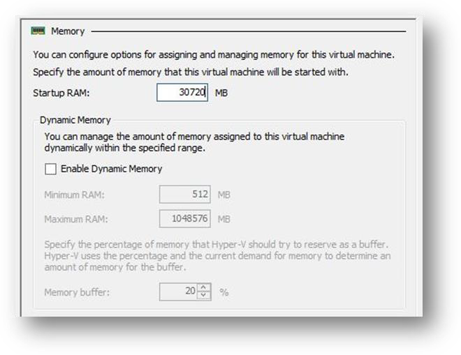
- When running a DataCore Server inside a Virtual Machine, do not enable Hyper-V's 'Dynamic Memory' setting for the SANsymphony Virtual Machine as this may cause less memory than expected to be assigned to SANsymphony’s cache driver.
- Fix the 'Startup RAM' to the required amount.
- Here is an example where a SANsymphony Virtual Machine has had its Startup RAM fixed to always use 30GiB on startup:
This does not apply to other Hosts running in Hyper-V Virtual Machines.
Processor
Reserve all CPUs used for the SANsymphony virtual machine by setting the “Virtual machine reserve (percentage)” to 100.
Microsoft Hyper-V Deployment Examples
This section provides example Hyper-V hyper-converged deployment configurations using Fibre Channel mirrors, with and without Microsoft Cluster Services, along with example IP networking layouts and related best practices.
Using Fibre Channel Mirrors
With Microsoft Cluster Services
Here is an overview of best practices for a ‘minimum configuration’ highly available, hyper-converged deployment installed on the Root/Parent partition when using Fibre Channel mirrors with Microsoft Cluster Services.
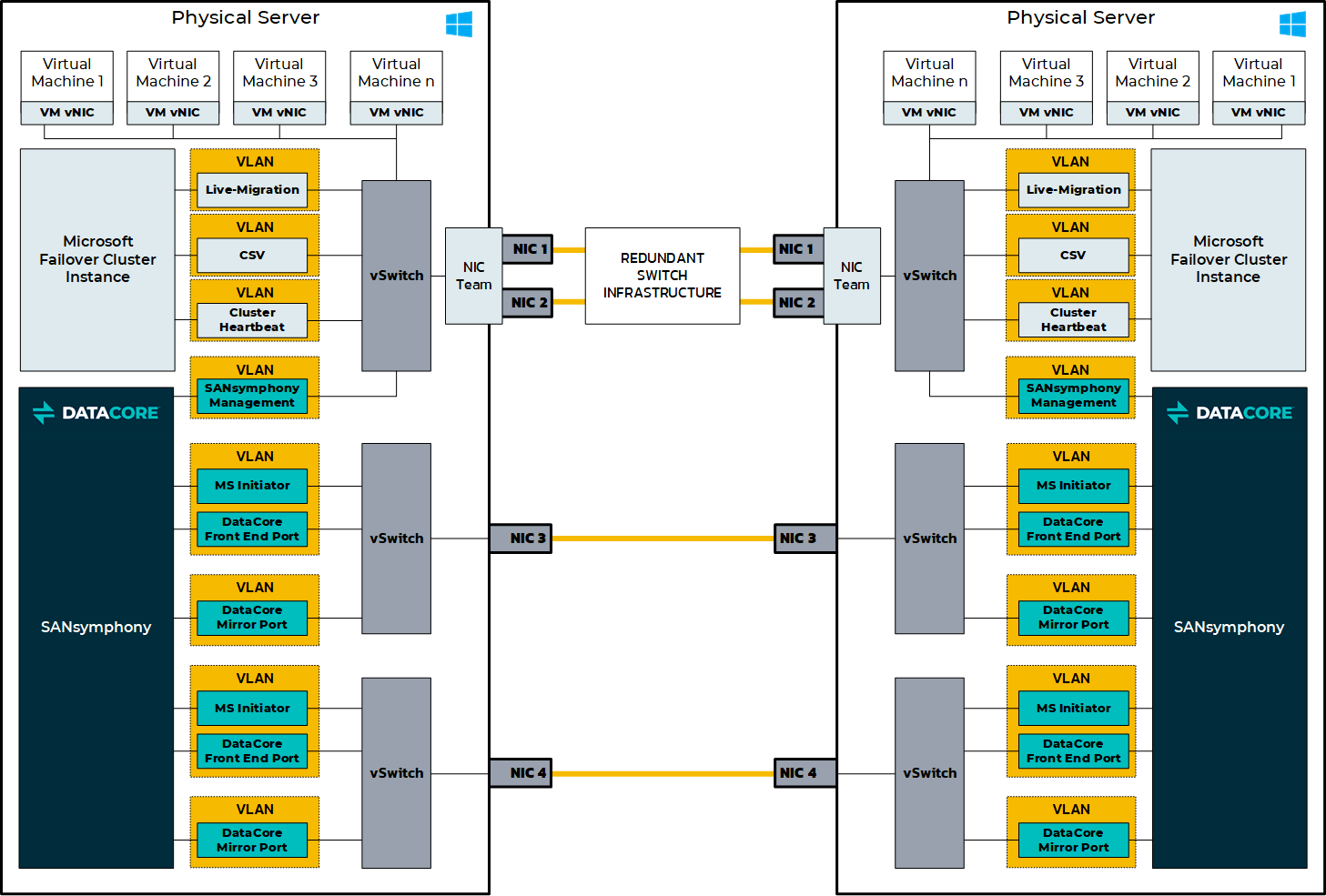
An example of the IP networking settings for this configuration is shown below.
An example of the IP networking settings when using Fibre Channel mirrors with Microsoft Cluster Services:
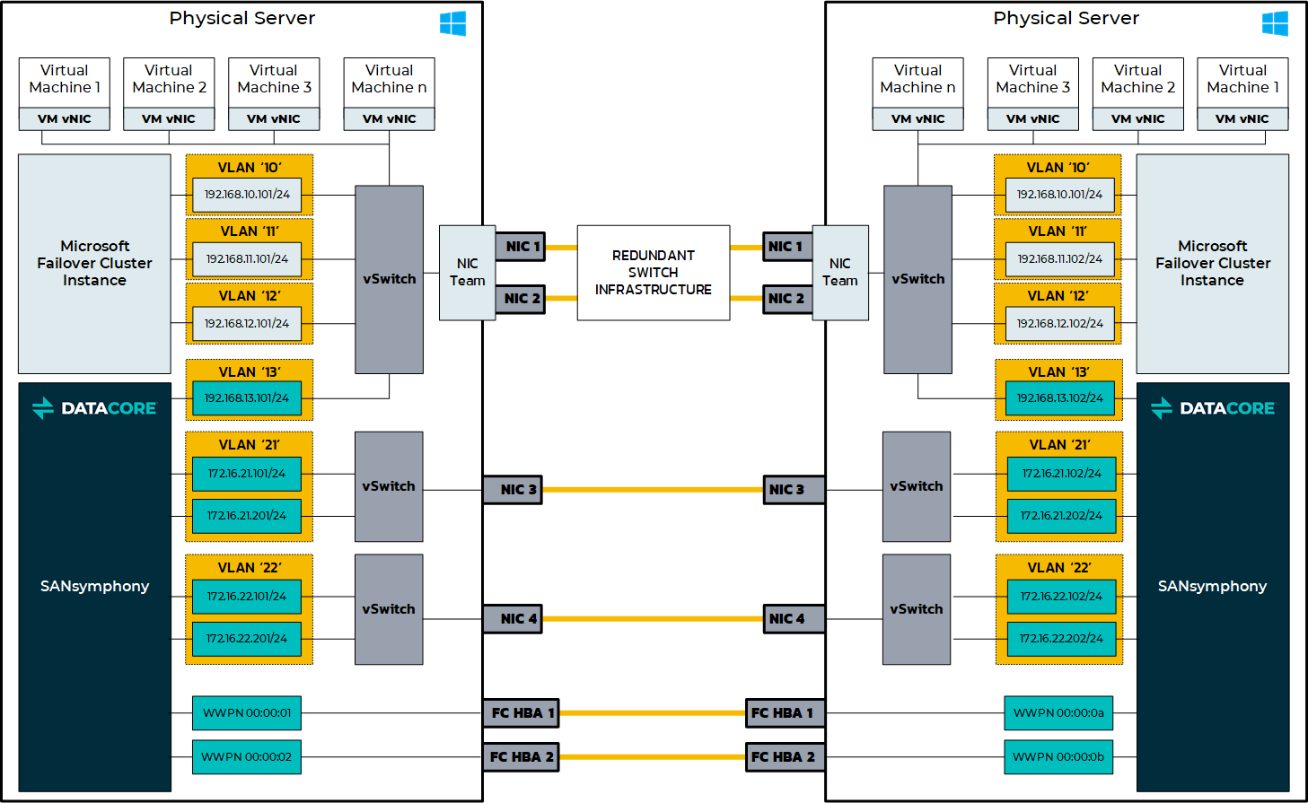
See more explanatory technical notes in the Microsoft Hyper-V Deployment Technical Notes section.
Without Microsoft Cluster Services
Here is an overview of best practices for a ‘minimum configuration’ highly available, hyper-converged deployment installed on the Root/Parent partition when using fibre channel mirrors without Microsoft Cluster Services.
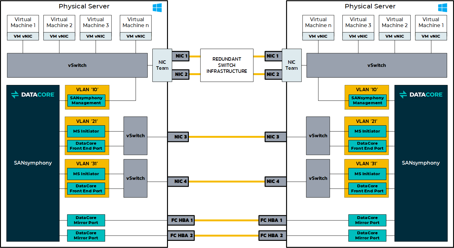
An example of IP networking settings for this configuration is shown below.
An example of IP networking settings when using Fibre Channel mirrors without Microsoft Cluster Services:
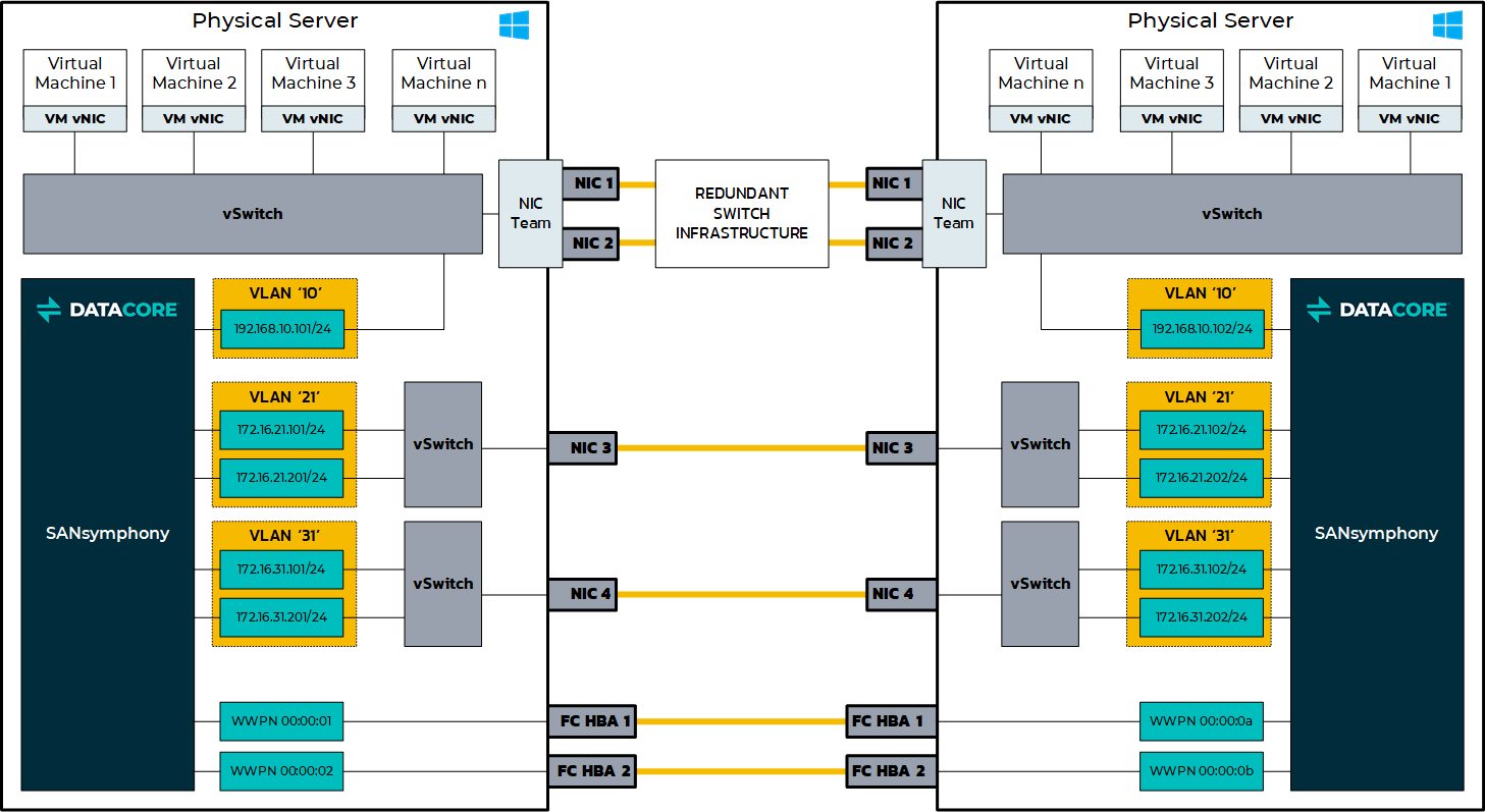
See more explanatory technical notes in the Microsoft Hyper-V Deployment Technical Notes section.
Using iSCSI Mirrors
With Microsoft Cluster Services
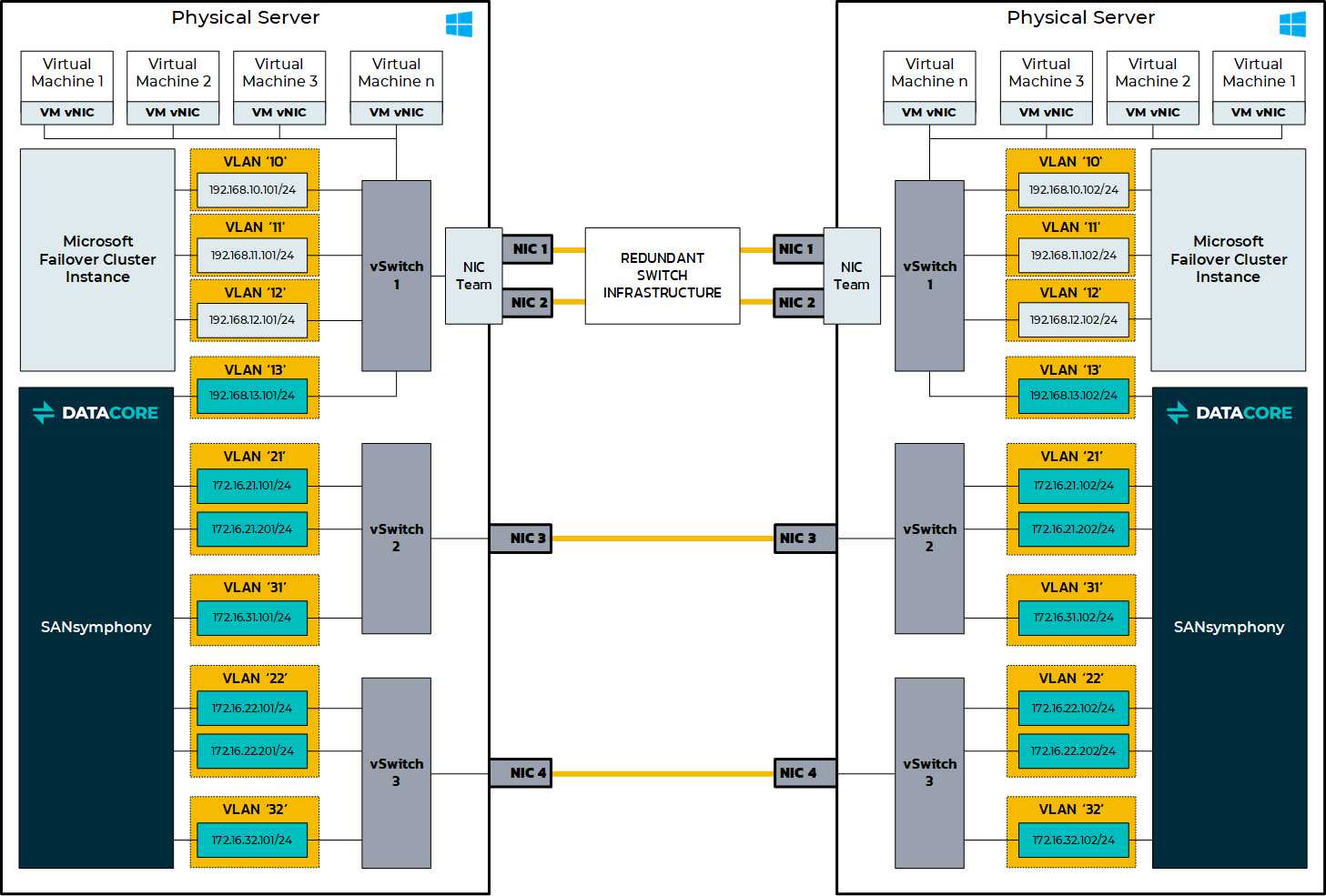
Here is an overview of best practices for a ‘minimum configuration’ highly available, hyper-converged deployment installed on the Root/Parent partition when using iSCSI mirrors with Microsoft Cluster Services.
An example of IP networking settings for this configuration is shown below.
An example of IP networking settings when using iSCSI mirrors with Microsoft Cluster Services:
Without Microsoft Cluster Services
Here is an overview of best practices for a ‘minimum configuration’ highly available, hyper-converged deployment installed on the Root/Parent partition when using iSCSI channel mirrors without Microsoft Cluster Services.
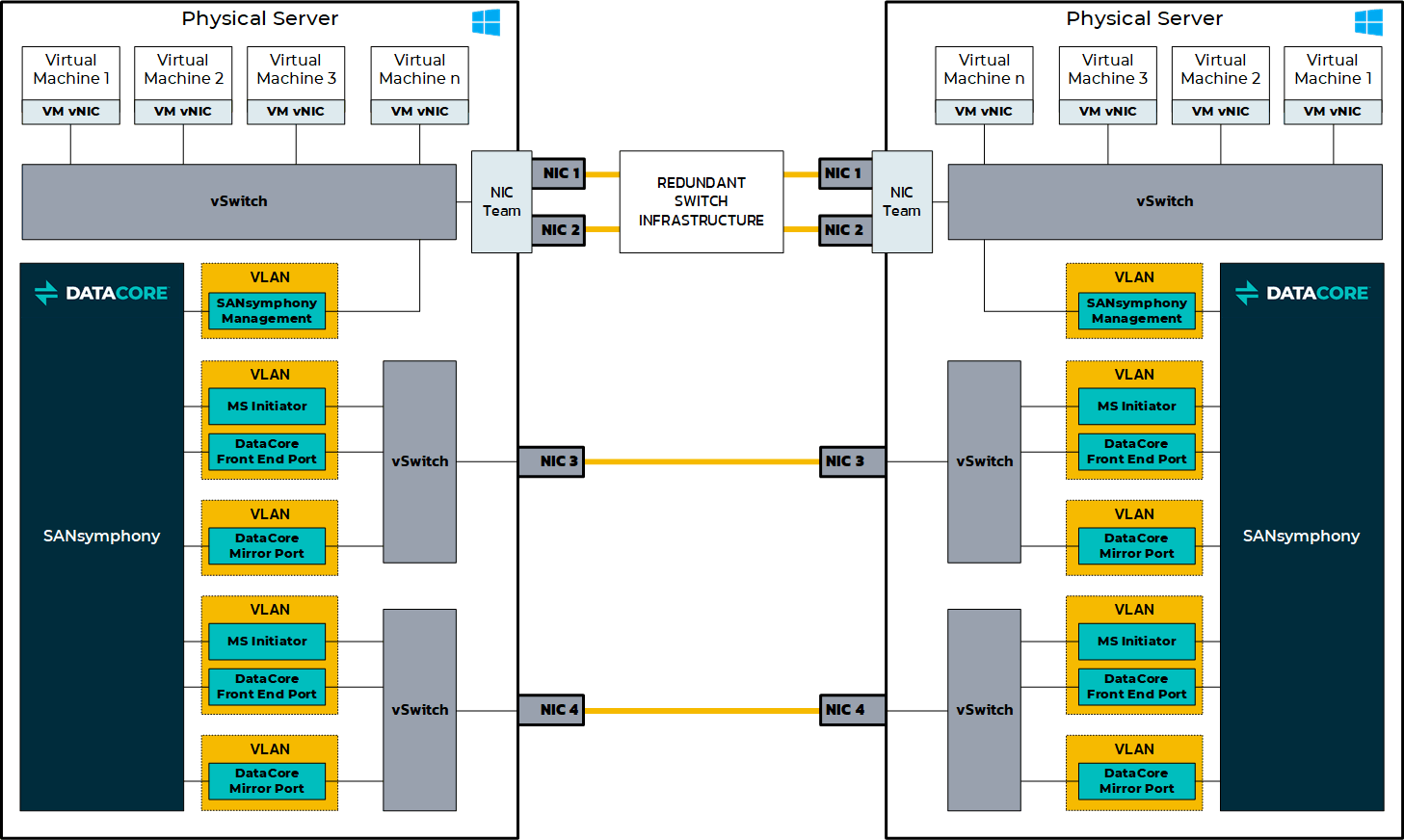
An example of IP networking settings for this configuration is shown below.
An example of IP networking settings when using iSCSI mirrors without Microsoft Cluster Services.
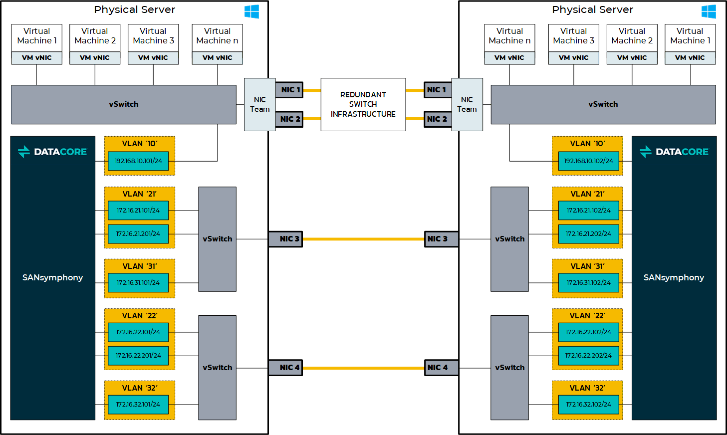
See more explanatory technical notes in the Microsoft Hyper-V Deployment Technical Notes section.
Microsoft Hyper-V Deployment Technical Notes
This section provides technical recommendations and networking best practices for Microsoft Hyper-V deployments, including NIC usage, iSCSI loopback configuration, initiator settings, and performance considerations for virtual and physical NIC environments.
NIC Teaming
DataCore does not recommend using NIC teaming with iSCSI initiator or target ports.
Refer to Using NIC Teaming with SANsymphony for more information.
MS Initiator Ports
While technically, the MS initiator is available from ‘any’ network interface on the DataCore Server, the convention here is to treat MS Initiator connections used explicitly for any iSCSI Loopback connections as a separate, dedicated, IP address.
Creating Loopback Connections
Using SANsymphony’s Built-in Loopback Ports
Do not use SANsymphony’s built-in loopback ports for serving virtual disks to the hypervisor. See Microsoft Hyper-V Deploymentfor more information.
Using iSCSI Connections
Always connect to a DataCore Front-end (FE) port never from it when creating an iSCSI loopback (i.e. never initiate from the same IP address as a DataCore FE port). Also make sure that the Microsoft initiator connection is initiating from a different MAC address than the DataCore FE port (i.e. do not create the Loopback ‘within’ the same NIC that has multiple IP addresses configured it).
While looping back on the same IP/MAC address technically works, the overall performance for virtual disks using this I/O path will be severely restricted compared to looping virtual disks between different MAC addresses.
Using Virtual NIC Connections
The following illustration is an example showing the correct initiator/target loopback connections (highlighted in red) when using virtual NIC connections (vNICs).
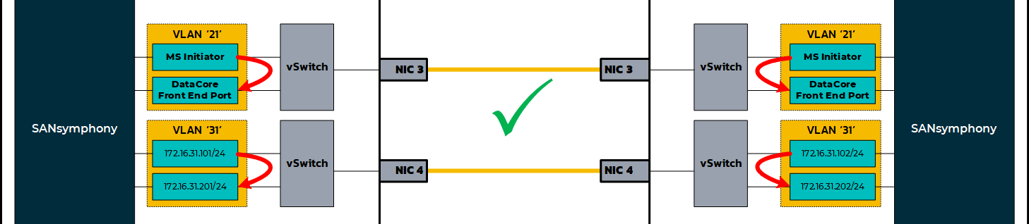
DataCore FE ports are never used as the initiator - only the target - and that the interface used for the Microsoft Initiator never connects back to itself.
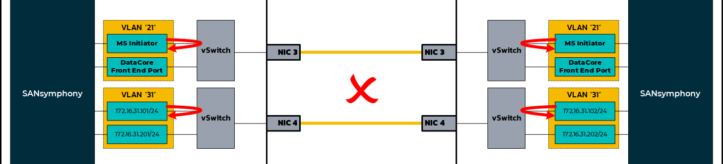
Here is the same example but with the incorrect initiator/target loopback connections (highlighted in red) when using vNICs.
Using Physical NIC Connections
With a physical NIC connections (pNICs) loopback connection both the Microsoft Initiator and the DataCore FE port each get assigned their own physical NIC which are both connected to an IP switch and logically connected to each other, creating the ‘loop’.
The following illustration is an example showing the correct initiator/target loopback connections (highlighted in red) when using pNICs.

DataCore FE ports are never used as the initiator - only the target - and that the interface used for the Microsoft Initiator never connects back to itself.

Performance using a vNIC Loopback compared to a pNIC Loopback
While DataCore have no preference over using virtual or physical NICs as loopbacks mappings, internal testing has shown that pNIC loopback configurations have been able to give as much as 8 times more throughput compared to vNIC loopback configurations under the same I/O workloads.
Maintaining Persistent Reservation connections (Microsoft Cluster Services)
If the DataCore Servers are configured within a Microsoft Cluster, an additional iSCSI Initiator connection is required for each MS Initiator designated vNIC/pNIC to ensure that all Cluster Reservations can be checked for/released by any server should the SANsymphony software be stopped (or unavailable) from one side of the high available pair.
Using the same MS Initiator IP address as those configured for iSCSI Loopback connections connect them into the corresponding ‘remote’ DataCore Server’s FE port as shown below. The following illustration shows the correct initiator/remote target connections (highlighted in red) when using vNICs.

The same correct initiator/remote target connections (highlighted in red) when using pNICs.

Unlike vNICs, an IP switch is required to provide both the ‘loop’ connection between the physical NICs and a route to the ‘remote’ DataCore FE port on the other DataCore Server.
SANsymphony’s Management connection
Avoid using the same IP address of any iSCSI port as SANsymphony’s Management IP address. Heavy iSCSI I/O can interfere with the passing of configuration information and status updates between DataCore Servers in the same Server Group. This can lead to an unresponsive SANsymphony Console, problems connecting to other DataCore Servers in the same Server Group (or remote Replication Group) and can also prevent SANsymphony PowerShell Cmdlets from working as expected as they also need to ‘connect’ to the Server Group to perform their functions.